These are the pics of the fairlane shocktower kit 1962-65


CRITES RESTORATIONS
13155 USR 23, ASHVILLE OH 43103
PH: 740-983-4777 FAX: 740-983-9691 Email: :tbolt427@verizon.net
WEBSITE: www.critesperformanceparts.com
ENGINE COMPARTMENT CONVERSION INSTRUCTIONS 1962-65 FAIRLANE OR METEOR FOR 390-427-428-429-460 ENGINES AND 351 SMALL BLOCKS
Tools: Cutting torch, soapstone marker, hand grinder, electric welder, wire brush, spring compressor, socket set, lug wrench, jack and jack stands, drill and 3/8” drill bit. We suggest spring compressor KD tool number 3450 or 3088. If you buy only one spring compressor, then you will need to design some type of jig to retain the one compressed position while using spring compressor to remove second spring. Be very careful as these long springs are hard to control and are dangerous if not removed correctly with proper tool. Do not get your body where you could be hit by spring should error be made upon removal or installation.
STEP 1: After engine and motor mounts are removed, remove front wheels, springs and shocks.
STEP 2: Remove steering column attachment under dash and bolts that hold steering gear box to frame. Push gear box out of the way of shock tower.
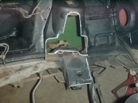
STEP 3: Place the fiberglass templates over the shock tower and using the wire brush, clean around edge of template and using soapstone, trace the edge of the template. (See photo #1)
STEP 4: Just above the base of the shock towers you will see 8 to 10 spot welds that must be drilled out or cut out with a torch. (See photo # 1)
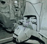
STEP 5: With torch remove area of shock tower outlined. See photo #2. Do not cut out the line as you will need a little material to grind down rough edge.
STEP 6: Photo #1 also shows 2 white lines where excess metal should be removed from motor mount base. Reweld edge after this cut. This step not required for 351 engine.
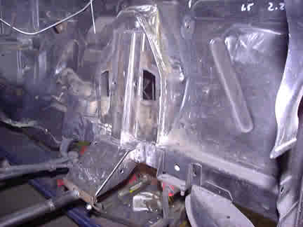
STEP 7: Photo #3 shows the 2 nuts that hold the A frame in place. Notice one nut has been shortened. Both must be shortened to 1 1/4” as one is shown. These nuts are hardened and are best cut with an abrasive cutting disk or bi-metal saw blade. Do not cut with torch as the torch will remove heat treating and soften the nuts.
STEP 8: Photo #4 shows a white line where the A frame platform must be cut. Check the A frame support gussets supplied in this kit as these pieces must be welded under platform later.
STEP 9: It is mandatory that a brace (see photo #5) now be designed to attach to the top of the shock towers to keep the original spread between towers. The welding process will shrink the shock towers if not braced apart. Do not remove spreader brace until welding is cold. Spread between shock towers at top inside, should be minimum 27 3/4 inches we suggest you spread shock towers 1/2 inch wider than stock to allow for extra shrinkage when brace is removed. 23 3/4 inches at the narrowest part of A frame support when completed.
STEP 10: Photo # 6 shows A frame gusset welded in place .
STEP 11: Photo #7 shows a cupped in area on (drivers side only) A frame platform for header tube clearance. This is important only on the big block applications 390-427-428 and should be done before final welding. This step is NOT required for the 460! This can be easily done by notching out a half moon notch (about 3/8 inch at the deepest part at the top) and then heating the gusset and hammering it back to fit the cup. Gussets should be welded in place before the cupping is done.
NOTE: We designed a crossmember that fits both C6 auto and 4 speed. See price sheet for crossmember and trans insulator plus other LIGTENING BOLT parts and accessories.
NOTE: Don’t be surprised to find you will need to do a small amount of relief grinding when engine, trans, and headers are installed. One example is the pointed top corner of the steering gear box must be ground back to allow for extra header clearance when using the 460 engine. Headers will not fit if Crites Restorations motor mounts and trans mounts are not used
NOTE: The only cast iron exhaust manifolds that will work on FE engines as a performance manifold are 428 CJ manifolds. I was not able to find a cast manifold that would work for the 429-460. Custom headers are suggested which Crites Restorations has available for FE and 429-460.
These are the pics of the Comet / Falcon shocktower kit completed.


1. Once the engine and trans. has been removed, the car must be raised and set on jack stands.
2. A good quality spring compressor (we recommend KD tool) is required to remove both springs at this time.
3. Unbolt both upper & lower A frames plus both tie rod end sleeves. Note the number of shims used where each upper A frame bolt through the shock tower. Save the shims for reuse.
4. Remove sway bar and strut rods. Save strut rods rubber bushings.
5. Now is a good time to clean inside and outside of the shock tower area. This will help make clean cuts with torch plus a clean surface is mandatory for welding.
6. The steering column and steering box must be unbolted from the frame and under dash to make room to work on driver side shock tower. No need to separate gear box from steering column of drag link.
7. We supplied 2 fiberglass templates to place over shock towers. Use a soapstone marking stick ( available from welder supply) and mark a line along the edge of the template. Make sure templates are kept tight against tower while marking cut lines.
8. Notice the bottom end of the templates stop at the top of the frame rail. At this point, the motor mount and lower A frame mount start and continue down over the inside edge of the frame rail. All the metal for mounting of the motor mount and lower A frame must be removed back to the frame rail. Carefully cut this metal away not damaging the frame rail. Grinding will be required to help properly remove weld spots on frame rail areas.
9. There is no need to cut into braces that run from the upper shock towers to the firewall.
10. Start the reassembly process by welding the large plate assembly to the shock towers. These 2 plates are cut a little larger at the openings and can easily be centered by allowing the same amount of flange around the opening on front and rear of shock tower. Base of plate will rest on top of frame rail. There is a left and right to these plates. Match the outside contours to the tower to identify left from right plates. Tack weld plates in place. Bottom of plates will hang over top side of frame rail about 1/2 inch.
11. Next the 2 lower A frame brackets are tack welded in place. These are marked L or R left is driver side. Notice that there are 2 holes on each frame rail (approx. 1/2 inch in diameter) right where you removed the old lower A frame attachment. Align the 2 holes in the new lower A frame brackets with the 2 holes in the frame rail and push up tight. Brackets should be close to that overhang from the shock plate so the base of the shock plate can be welded to top of lower A frame brackets and to frame rail This will help tie all pieces together for strength. Bolt the tubular crossmember to the lower A frame brackets. Now weld the plates and brackets permanent. It is mandatory that the shock tower large plates be welded both inside and outside of the shock tower. Be sure and weld base of shock tower plate to top of lower A frame bracket. This will give you added strength when these 2 pieces are welded together.
12. If you plan to replace the 2 swivel brackets at the base of the coil springs, now is the time to replace them. We have these in stock if you didn’t order them with your kit.
13. Bolt upper & lower A frames in place. Be sure to reinstall the alignment shims exactly the same as they were. Bolt lower A frame in place. Install the new coil springs. Attach tie rod ends to tie rods. Keep in mind the spindles are now farther apart and there will be less tie rod threads for tie rod sleeves. Be sure you have an even amount of thread inside the sleeve.
14. In step #4 you unbolted the strut rods. Now turn to the brackets where the front of the rods are attached to the front of the car. Since you will widen the width of the spread between the front wheels, the strut rod will come up short. To correct this, remove the metal around the hose where the rubber bushing on front of the strut rods is mounted. We have supplied 2 replacement pieces to weld back inside the channel. The 2 gusset plates (2 11/16 in. X 2 3/4 in. X 3/8 in.) should be welded in place. These hold the front end of the strut rod. The new gussets should be set approx. 3/4 inch to the rear of the center of the old gusset you removed. It would be helpful to install the strut rods and rubber bushings to be sure the 3/4 inch rearward movement of the new gussets is enough. Weld gussets in place and reattach strut rods when weld area is cold.
15. Reattach steering and you are done except exact alignment by a quality alignment dealer.